
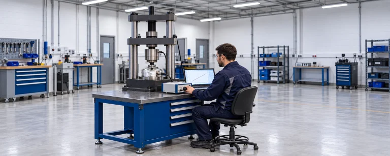














Connecting a sensor to a PLC: preserving resolution and sampling performance
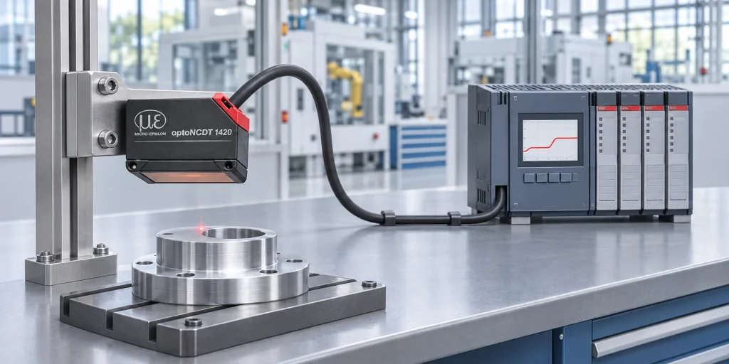
To preserve resolution and sampling performance when connecting a sensor to a PLC, check the entire measurement chain. For an analog path, calculate the quantization step from the signal range actually used, then assess input accuracy and noise. For a digital path, verify that the data format, transfer rate and synchronization meet the application requirements.
By Michael Gold, Elina Technologies. Technically edited from the original article.
A displacement sensor can deliver stable readings while the PLC value jumps or updates too slowly. Before replacing the sensor, check its output, the cable, the input card or interface module, and the PLC software.
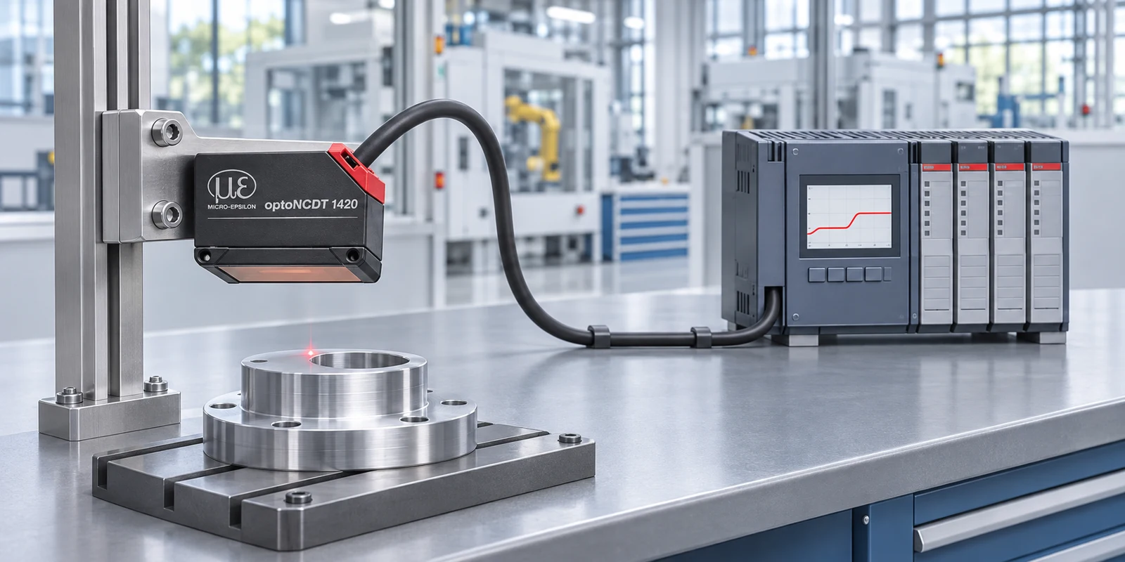
For an initial overview of interface choices, see Fieldbus or analogue: how to connect a sensor (opens in a new tab). This guide focuses on checking resolution, error and timing in the selected signal path before integrating it into a system.
What should you check in each sensor-to-PLC signal path?
Analog output: 4–20 mA or 0–10 V
The sensor or its controller converts the measurement to current or voltage. The analog input card converts the signal to a number, and the PLC software scales it to engineering units. Check output and input resolution, ranges, accuracy, filtering and wiring. For a current loop, also check load resistance and the voltage budget; for a voltage input, check input impedance and ground potential differences.
Serial digital interface: for example, RS422
The measurement is transmitted as numerical data. RS422 defines an electrical interface; it does not by itself guarantee a protocol the PLC can read. The receiver must support the sensor protocol, communication rate, frame decoding, scaling and error indicators. The transmitted word length is not proof of measurement accuracy or usable resolution.
Industrial Ethernet: PROFINET, EtherNet/IP or EtherCAT
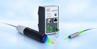
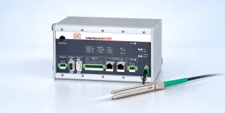
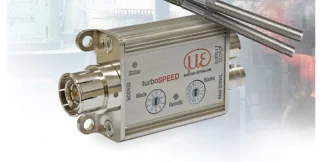
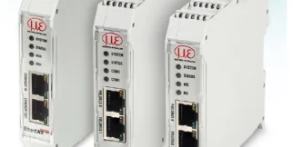
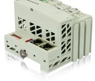
The interface may be integrated into the sensor or provided by a compatible gateway. The Micro-Epsilon IF2035 family (opens in a new tab) includes variants for these protocols. Select the specific variant compatible with the sensor and network; a module for one protocol is not necessarily a multiprotocol module.
How do you calculate resolution in an analog measurement chain?
The following is a design calculation, not the specification of a particular sensor or input card. Assume that a 50 mm measuring range maps to the full working range of an ideal converter, with no reserved codes and all converter codes used. The approximate quantization step is:
q ≈ L / 2B
Here, L is the mapped engineering range and B is the number of bits. The exact mapping depends on the manufacturer’s code convention. A quantization step is neither accuracy nor repeatability.
| Mapped range | 12 bit | 16 bit |
|---|---|---|
| 50 mm | 12.21 µm per step | 0.763 µm per step |
| 10 mm | 2.44 µm per step | 0.153 µm per step |
If the sensor output is 16 bit and the input is 12 bit, both conversions contribute to the result. The complete chain should not be described as an accurate 16-bit measurement. Checking the coarser converter is useful as an initial screen, but it does not replace a complete error budget.
Why does the PLC input card’s range matter?
When 4–20 mA maps to 50 mm, a change of 1 µA represents 3.125 µm. A 5 µA signal change is therefore equivalent to 15.625 µm, and 10 µA to 31.25 µm. These are unit conversions, not predictions of noise in a particular system.
If a 12-bit card allocates all its codes to 0–20 mA, a 4–20 mA signal uses only 80% of that range. The ideal current step is approximately 4.883 µA, equivalent to 15.26 µm over this engineering range. Do not automatically use 12.21 µm merely because the card is labelled “12 bit.”
Input accuracy is not the quantization step
For illustration only, assume a card error of ±0.1% or ±0.3% of a full engineering span of 50 mm. The equivalent errors are ±50 µm or ±150 µm, respectively. If the percentage refers to a different electrical span, to the reading, or includes an additional offset, recalculate using the manufacturer’s definition.
Also assess offset, gain error, linearity, thermal drift and noise. Adding absolute bounds can provide a conservative estimate when they are defined consistently. Statistical combination requires assumptions about distributions and dependencies; these quantities should not all be added as if they were identical.
When should you narrow the analog output window?
If the application uses only a 10 mm window and the sensor supports suitable teaching or scaling, mapping that window to the full output span can reduce the engineering-unit step. With the same full-code-use assumption, 16 bit gives approximately 0.153 µm per step. For 4–20 mA mapped to 10 mm, 1 µA represents 0.625 µm.
Scaling does not improve the sensor’s optical accuracy or eliminate noise. Check out-of-window operation, fault behaviour and safety margins. Follow the sensor and input-card manuals for wiring, shielding, grounding and separation from power cables; no single grounding arrangement suits every system.
Does a digital connection preserve every sample?
Not necessarily. Distinguish sensor measuring rate, data transfer rate, bus cycle and PLC task cycle. Sensor filters, queues, synchronization and buffering also affect data age and latency.
In an ideal example, a 4 kHz sensor generates four samples per millisecond. If the interface transfers only the latest value during each 1 ms cycle, the PLC does not receive the three intermediate samples. This follows from the selected operating mode, rather than being an unavoidable property of every network or protocol.
The IF2035-EtherCAT documentation describes transferring multiple samples per cycle through oversampling. Section 5.6 of the manufacturer’s manual, page 22 (opens in a new tab), includes the 4 kHz/1 ms example with a factor of 4. In that manual, support is described for the RS422 sensor interface. Verify data mapping, synchronization and the actual hardware and firmware versions.
Even when all samples are transferred, they may arrive together after buffering. Preserving the sample sequence is not the same as reducing latency. A fast control application needs a separate end-to-end response-time check.
Practical comparison: analog, RS422 or Industrial Ethernet
| Consideration | Analog | RS422 | Industrial Ethernet |
|---|---|---|---|
| What reaches the PLC? | An electrical signal converted at the input | Data in the sensor protocol | Process data in the selected mapping |
| Resolution checks | Output, input and code-range utilization | Encoding, scaling and usable measurement information | Format, mapping and scaling |
| Timing checks | Filtering, conversion and input acquisition rate | Data rate, frames and queues | Bus cycle, synchronization, buffering and PLC task |
| When to consider it | When error and timing budgets are adequate and a suitable input is available | When the receiver supports the required protocol and rate | When integration with the control network and its features is required |
How to select the connection in practice
- Define the measurement task: working range, tolerance, smallest change to detect and response-time requirement. Distinguish a tolerance specified as ±a value from the full tolerance interval.
- Identify the exact chain: sensor model, output variant, input card or gateway, cable, PLC and relevant versions.
- Build error and timing budgets: include both the sensor and connection. No single fixed ratio between tolerance and quantization step suits every task.
- Test on the actual part: compare the sensor reading with the PLC value during motion and under working conditions. Check excursions, communication loss and invalid-value indicators.
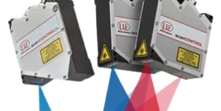
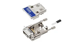
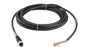
For equipment options, see laser displacement sensors (opens in a new tab) and Micro-Epsilon interface accessories at Elina (opens in a new tab). Module compatibility must be checked for the specific sensor–interface pair and required configuration.
Frequently asked questions
Can 4–20 mA support micrometre-level measurement?
It can, provided the complete chain meets the requirement: sensor, output, wiring, input and scaling. A nominal 16-bit resolution alone does not establish suitability.
Is a 16-bit input more accurate than a 12-bit input?
Its nominal quantization step is smaller over the same utilized range, but accuracy also depends on noise, offset, gain, temperature and the card specification. Compare equivalent conditions and units.
Does EtherCAT guarantee every sample reaches the PLC?
The protocol name alone does not guarantee this. Check that the sensor, interface, data mapping and PLC software support the required rate and transfer mode. Configure synchronization and oversampling where needed.
What information is needed to select a sensor interface?
Sensor model and version, available outputs, PLC model and input card or network, working range, tolerance, rate and latency requirements, cable length and environmental conditions.
Planning a sensor-to-PLC connection?
Contact Elina Technologies for an application review (opens in a new tab) with the sensor, PLC and measurement-task details. This allows the signal path and its limits to be assessed before choosing components.
Technical sources
- Micro-Epsilon IF2035 family (opens in a new tab): interface variants and general compatibility.
- IF2035-EtherCAT, section 5.6 (opens in a new tab): transferring multiple samples per cycle and support limitations.
The numerical examples are ideal calculations with explicit assumptions. They are not test results or product performance commitments.