

















Displacement sensor or accelerometer: how to choose for vibration measurement
Frequency alone does not choose the sensor. Define the measurand, amplitude, reference and bandwidth before selecting a vibration measurement system.
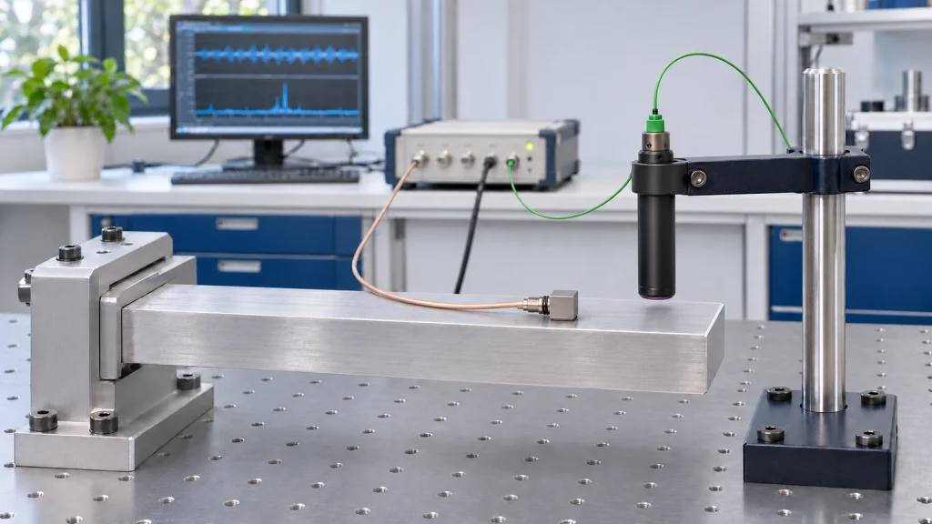
To choose a vibration sensor, first define the measurand: a changing gap relative to a probe mount, or acceleration at a point on the part. Then assess frequency range, amplitude, measurement noise and installation. Frequency alone does not decide between a displacement sensor and an accelerometer.
By Michael Gold, Elina Technologies. Technically edited from the original article.
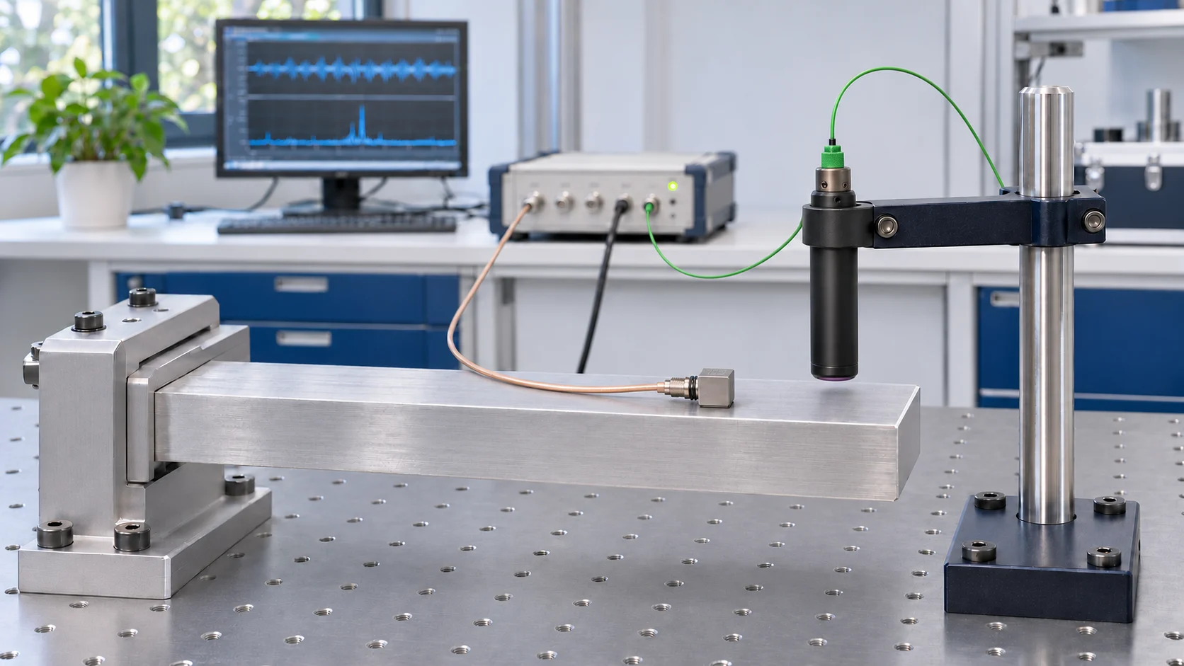
A request for a “vibration sensor” should begin with a practical question: how far does the part move, and relative to what? Motion that is readily measured as a changing gap at low frequency may become very small at high frequency, even with the same acceleration amplitude. A fast displacement sensor can nevertheless suit high-frequency measurements when its range, noise and frequency response meet the requirement.
How do you convert acceleration to displacement for sinusoidal vibration?
For sinusoidal motion at a single frequency, acceleration amplitude and displacement amplitude are related by:
xₚ = aₚ / (2πf)²
Here, xₚ is peak displacement in metres, aₚ is peak acceleration in m/s², and f is frequency in hertz. The following example uses aₚ = 1g₀ = 9.80665 m/s². These are calculations, not test results or a sensor specification.
| Frequency | Peak displacement at 1g peak acceleration |
|---|---|
| 10 Hz | 2.484 mm |
| 100 Hz | 24.84 µm |
| 500 Hz | 0.994 µm |
| 1 kHz | 0.248 µm |
| 5 kHz | 0.00994 µm, approximately 9.94 nm |
With acceleration held constant, increasing frequency tenfold reduces displacement amplitude by a factor of one hundred. With displacement held constant, acceleration instead increases with frequency squared. Identify which quantity remains constant in a comparison.
Peak, peak-to-peak or RMS?
For a sine wave, peak-to-peak displacement is twice its peak amplitude. The first row therefore corresponds to approximately 4.968 mm peak-to-peak. Peak amplitude is √2 times the RMS value. The conversion formula also works for sinusoidal RMS values when both acceleration and displacement use the same convention. Do not enter RMS acceleration and label the result peak displacement.
For vibration containing several frequencies, there is no single frequency to insert alongside the overall acceleration. Individual frequency components can be analysed separately; reconstructing a displacement time signal also requires attention to phase, filtering and integration conditions.
What is the measurement reference?
A non-contact displacement sensor measures the changing gap between the probe and its target. If the probe mount also moves, that relative motion enters the result. For a shaft measured against a bearing housing, the relative gap may be exactly what is required. In a laboratory measurement, a vibrating probe bracket can introduce an error relative to the intended reference.
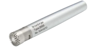
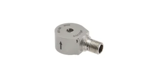
An accelerometer measures acceleration at its mounting point and along its sensitive direction. It does not directly measure a gap to an external target. Select the axis, mounting position and signal chain accordingly: measuring a bearing housing is different from measuring the shaft orbit relative to that housing.
A piezoelectric accelerometer measures dynamic acceleration, with a lower frequency limit determined by the sensor and electronics. Very slow or constant acceleration may call for another type, such as a MEMS accelerometer supporting DC. That still does not provide a direct static position measurement.
Bandwidth versus sampling rate: what must you check?
Bandwidth describes the measurement system’s response at different frequencies; sampling rate describes how many values are acquired per second. A high sample count does not establish that the sensor, controller and filters reproduce the required vibration amplitude and phase.
Check the complete chain: sensor, controller or amplifier, output, acquisition system and processing. Sampling must suit the highest relevant frequency and the anti-aliasing filter. Meeting the Nyquist condition alone is not a system accuracy check; amplitude and phase requirements may need additional design margin.
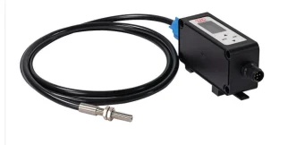
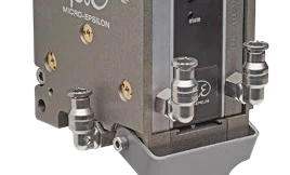
The Micro-Epsilon eddyNCDT 3060/3070 family (opens in a new tab) illustrates this distinction: the manufacturer specifies frequency response up to 20 kHz. This must not be substituted for an interface update rate, nor taken as proof of an acceptable amplitude error throughout that range. Check the model, filter setting and specification conditions.
Which resolution figure matters for vibration?
Compare expected displacement with noise and resolution under the required dynamic conditions. A static figure obtained with strong filtering may not apply to a fast measurement. Check whether noise is stated as RMS or peak-to-peak and over which bandwidth. No fixed amplitude-to-resolution ratio alone guarantees suitability for every application.
How do the installation and test part affect selection?
An accelerometer, mounting hardware and cable add mechanical loading. On a light part, such as a thin cantilever, they can change the response being measured. Attachment also affects frequency response. Assess local dynamic mass, mounting stiffness and cable routing, rather than just the total machine weight.
A non-contact displacement sensor adds no mass to the target. It still needs access to a surface and conditions appropriate to its technology: a conductive target for eddy current, suitable target geometry for capacitive sensing, or a suitable optical return for laser sensing. Dirt, coatings, temperature and changing angles affect each method differently.
On a rotating shaft, a non-contact probe measures a gap without attaching a cable to the moving target. An accelerometer mounted directly on a rotating part needs appropriate mounting and signal transfer. An accelerometer on the housing can answer a housing-vibration question, but does not automatically substitute for a shaft-motion measurement.
| Consideration | Non-contact displacement sensor | Accelerometer mounted on the part |
|---|---|---|
| Direct measurand | Gap relative to the probe mount | Acceleration at the mounting point and selected axis |
| Slow and static motion | Possible with suitable technologies and configurations | Piezoelectric types have a low-frequency limit; other types may support DC |
| Light parts | No mass loading of the target | Assess sensor mass, attachment and cable effects |
| Rotating target | Gap measurement without attachment to the target | Direct mounting and signal transfer need a suitable solution |
| Main checks | Reference mount, target surface, range and dynamic noise | Position and axis, attachment, acceleration range and chain response |
Five checks before choosing a vibration sensor
- Define the measurement question: gap, shaft motion relative to housing, structural acceleration or another quantity; specify direction and reference.
- Describe the signal: frequency range, amplitude, and peak or RMS convention. For a single sine wave, calculate expected displacement too.
- Check range: account for slow motion, changing gap, start-up, shock and excursions as well as the small vibration of interest.
- Check the chain and installation: amplitude and phase response, noise, filtering, sampling, surface, stiffness, mass and cable.
- Validate on the real part: assess results under operating conditions against the measurement requirement. Comparing two methods requires consistent measurement position, axis, filtering and synchronization.
Further reading: eddy current measurement through oil and dirt (opens in a new tab) and why datasheet accuracy differs from system performance (opens in a new tab). For control-system integration, see preserving resolution and sampling when connecting a sensor to a PLC (opens in a new tab).
Frequently asked questions
Should you always choose displacement below 100 Hz?
No. Frequency is one consideration. Amplitude, target access, measurement reference, noise and mounting can lead to a different choice. Check system performance over the required range.
Can a laser displacement sensor measure vibration?
Yes, when frequency response, measurement noise, acquisition rate and surface return suit the application. A high measuring rate alone does not establish capability.
Does double integration of acceleration provide displacement?
It can provide a displacement estimate over a defined frequency band. Offset, low-frequency content and initial conditions can cause drift; filters also change the wanted signal. Define and validate the processing. For a sine wave, compare the result with the amplitude calculation.
How do you measure a shaft orbit relative to its bearing housing?
A common arrangement uses two non-contact gap probes along perpendicular directions. Calibrate the axes and synchronize acquisition to obtain an orbit in that plane. Check surface effects and runout as well: not every change in gap represents vibration alone.
What information is needed for an application review?
Frequency range, amplitude and units, signal type, direction and reference, part material and mass, installation image, temperature and acquisition system. For displacement, state whether it is relative to another part or to an external reference.
Sources and application support
- Brüel & Kjær — Piezoelectric Accelerometers and Vibration Preamplifiers (opens in a new tab): vibration quantities and integration, section 3.7.1, printed pages 72–75.
- Brüel & Kjær — Transducers and Conditioning (opens in a new tab): position, attachment and mass loading, Accelerometer Mounting Solutions.
- Micro-Epsilon — eddyNCDT 3060/3070 (opens in a new tab): dynamic displacement sensing family.
Choosing how to measure vibration on your part? Contact the Elina Technologies team (opens in a new tab) with the measurement-task details to assess a suitable technology and configuration.